Design an arbitrary counter that counts or follows in this sequence:
0, 2, 4, 5, 7, 0, 2, 4........
It is pretty clear from the question that counter counts in,
0 -> 2 -> 4 -> 5 -> 7 -> 0 -> 2 -> 4 -> …….
It goes from 0 to 2 then 4 this way. After reaching 7 it goes back to beginning of the sequence and repeats the sequence.
Arbitrary Counter State Diagram:
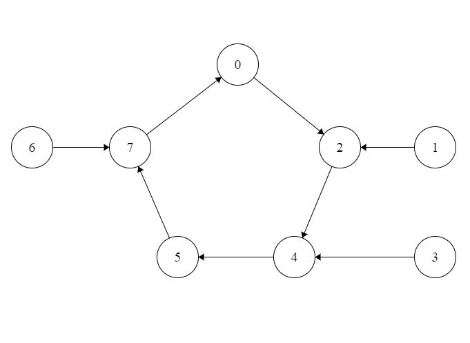

Since nothing is said about what will happen if it had to transition from 1, 3 and 6. So I can choose on my discretion what the next state will be from those unused states.
Arbitrary Counter State Table:
When simplifying input equations, unused states can be used as don’t care conditions or it may also be assigned specific next states. Here unused or unreachable states are 1, 3, 6 so these states can have any assigned next state of designers choice.
The reason or advantage of using don’t care is easier state diagram, smaller state table, easier k-map equations as well as less connections in the logic diagram etc.
There is also a good reason to use specific next states from unreachable states instead of using don’t care conditions. Such as during operation due to outside interference the may reach an unused state and break the intended sequence. Also it may keep circulating in unused states and never come back to original sequence.
Here I have only shown K Map and Logic Diagram using don’t care term for transition of unused states and using J-K Flip Flops.
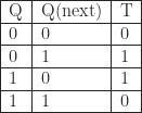
Excitation Table:
The excitation table below are for J-K, D, S-R, T latches. For making arbitrary counter with these latches fill the state table from the excitation table.
J-K:

D:
For D latch the next state is the output.

S-R:

T:
How to complete the state table:
First thing is to complete the present state. Since we have only 0, 2, 4, 5, 7 to count, fill in their binary representation. No need to show the rest or like I mentioned above.
Next, Fill up the next state based on present state. Like shown in the state diagram above from 0 it next counts to 2, then 4, then 5 etc.
So next state of 0 is 2. Which in binary is 000 to 010. Similarly 7 counts to 0. So in binary 111 to 000.
Last step is filling up Flip Flop inputs. If you use any other Flip Flops the above steps are always required. Just replace J-K latch here with any other latch and use excitation table to complete the state table.
Jc and Kc should be filled only based on present state of C and the next state of C. Similarly for others.
For example, 2 moves to 4. So,
Present -> Next
C B A -> C B A
0 1 0 -> 1 0 0
Here, C’s present state is 0 and next state is 1. So based on J-K excitation table the value will be 1 X.
State Table Not Showing Don’t Care Conditions:
Present State |
Next State |
Flip Flop Inputs |
|||||||||
| C | B | A | C | B | A | JC | KC | JB | KB | JA | KA |
| 0 | 0 | 0 | 0 | 1 | 0 | 0 | x | 1 | x | 0 | x |
| 0 | 1 | 0 | 1 | 0 | 0 | 1 | x | x | 1 | 0 | x |
| 1 | 0 | 0 | 1 | 0 | 1 | x | 0 | 0 | x | 1 | x |
| 1 | 0 | 1 | 1 | 1 | 1 | x | 0 | 1 | x | x | 0 |
| 1 | 1 | 1 | 0 | 0 | 0 | x | 0 | x | 1 | x | 1 |
How to Interpret the Table Above to Generate K Map:
Since this has only three bits. Create a three variable K-Maps. There will be a total of 6 K-Maps since there is two inputs per latch.
Also here 1, 3, 6 are don’t care, so fill these with x. Next 0, 2, 4, 5, 7 these positions are empty in k map. Fill in these position with values from the columns.
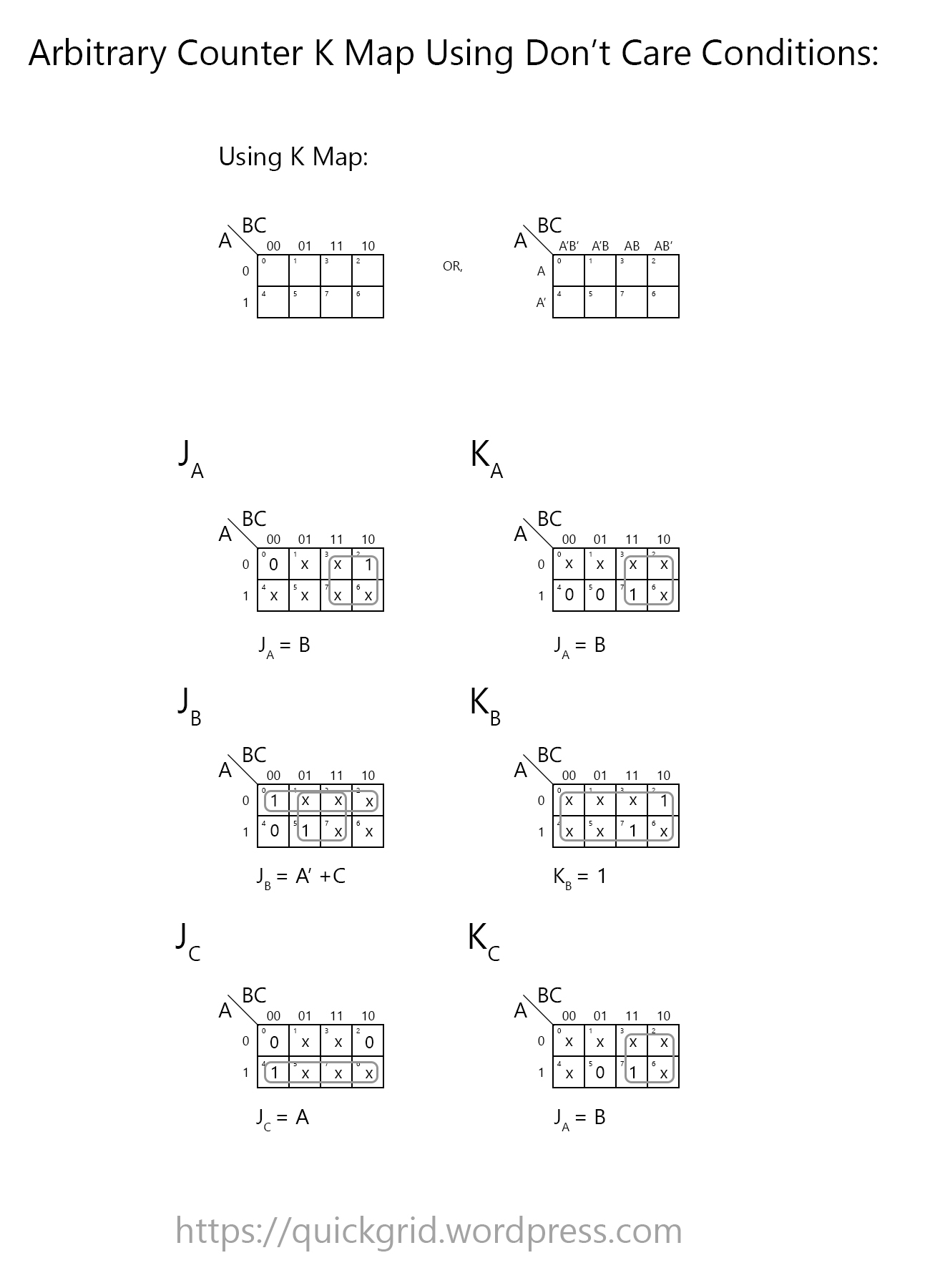
Karnaugh Map Using Table For Unused Don’t Care Conditions:
Here I have shown the table for don’t care terms for unused states transition to next states. For using specific state transition from unused states set the value from the table above in appropriate place and get the equation. From that equation create the logic diagram.
How to Connect the latches from K Map equations:
Here each of the latches are given a name A, B, C. Each of the latches represents a bit. Where C is the Most significant bit (MSB) and A is the least significant bit (LSB). The input of J-K latch for A are JA and KA. Similarly for others.
The next states depends on current state. The output is on the right side. What ever the value of the output on the top output is the bottom one is the prime (opposite) of it.
From the K Map set connections on the left side ( input ) to right side ( output ). This is assuming that the Flip Flop is positioned like shown in the diagram below. Although This may not always be the case.
Logic Diagram From the above Karnaugh Map Using Don’t Care For 1, 3, 6 states:
Here I’ve drawn the logic diagram in logisim. If you draw by hand it hand the design will be the same just replace the button with a clock.
Make sure input of KB is always 1. Because that’s the equation for KB in Karnaugh Map.

How to check if the Arbitrary counter is working:
Download the arbitrary counter logisim circ file from here.
Select the hand tool below File menu. Also make sure input of JB is set to 1. Now click on the button to give clock pulse.

You must be logged in to post a comment.